Mosfet Analog Switch Circuit Circuit Diagram MOSFETs exhibit high input impedance, making them versatile and adaptable to various applications. How to Use MOSFET as a Switch. To use a MOSFET as a switch, you need to ensure that the gate-source voltage (Vgs) is higher than the source voltage. When the gate is connected to the source (Vgs=0), the MOSFET remains off. The operation of the enhancement-mode MOSFET, or e-MOSFET, can best be described using its I-V characteristics curves shown below. When the input voltage, ( V IN) to the gate of the transistor is zero, the MOSFET conducts virtually no current and the output voltage ( V OUT) is equal to the supply voltage V DD.So the MOSFET is "OFF" operating within its "cut-off" region.

In broad strokes, a MOSFET device allows us to use a relatively low voltage at the gate to modulate current flow from drain to source. Two basic types of MOSFETs are bought as discrete devices
MOSFET Design Basics You Need To Know (Part 1) Circuit Diagram
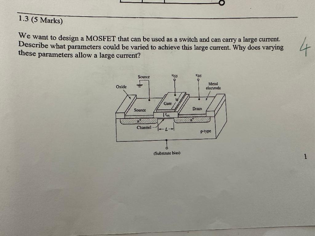
In this project, we will go over how to connect an N-Channel MOSFET to a circuit for it to function as an electronic switch. The type of N-Channel MOSFET we will use is the enhancement-type MOSFET, the most commonly used type of MOSFET. MOSFETs, like BJTs, can function as electronic switches. Although unlike BJTs, MOSFETs are turned on, not by Semiconductor switching in electronic circuit is one of the important aspects. A semiconductor device like a BJT or a MOSFET are generally operated as switches i.e., they are either in ON state or in OFF state. Ideal Switch Characteristics. For a semiconductor device, like a MOSFET, to act as an ideal switch, it must have the following features: When the gate voltage is lower than the threshold no such channel exists and the switch is considered as open. Two types of MOSFET devices can be identified. The n-channel MOSFET shortly NMOS and p-channel MOSFET shortly PMOS. The NMOS transistor contains n+ drain and source regions which are placed on p-type substrate as shown in Figure.
In most cases, you can use the same power supply that you are using for your high power device to operate the MOSFET as well, using a mechanical switch to apply the gate voltage. The image below shows exactly that type of application. (Alternatively, you can also use an electronic signal, like from a microcontroller, to activate the MOSFET

Designing MOSFET Switch - Comprehensive Circuit Diagram
Technical explanation MOSFET driver. Relay driver using MOSFET detailed design and analysis. MOSFET low side driver design. Comprehensive MOSFET driver design. Technical explanation MOSFET driver. Now, we will start our objective which is designing MOSFET switch. We are going to use the circuit in Figure 4 for reference. Step 1: Know the