How to make Wireless Control 14 Channel at your Fingertips Circuit Diagram With the right set of components and a bit of patience, you can create your own unique remote control - and start using it right away. Wireless Rf Remote Control On Off Switch. Remote Control Circuit Through Rf Without Microcontroller. Circuit Zone Com Electronic Kits Projects Schematics Diy Electronics. Using the 700 Series, electrical engineers can create and design their own custom RF remote control system to remote switch a range of Industrial application

Designing radio frequency (RF) remote controls has never been easier thanks to the advent of highly-integrated, single-chip RF solutions. System-on-chip (SoC) transmitter solutions, such as Silicon Labs' Si4010 single-chip remote control integrated circuit (IC), greatly simplify the process of designing a remote control and reduce system bill of materials (BOM) cost by eliminating the need

RF remote control using Arduino and 433mhz ASK module Circuit Diagram
Point your IR remote control at the TSOP312 receiver module. Press any button on the remote control. You should see the relay click and its onboard LED will turn ON. Press the button again. The relay should click again, and the LED will turn OFF. Note that this circuit can be a bit sensitive to noise from other IR sources. An RF remote controller is a device that can be used to switch ON/OFF equipment or devices wirelessly using radio frequency transmission. The remote or transmitter part is a handheld device that has switches or other input options to select the operation. Single device RF remote control Transmitter. Remote transmitter circuit - figure 1
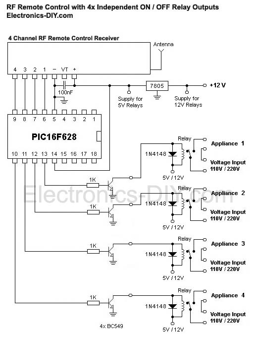
Use the remote control to send signals to the 433MHz RF receiver module. You should be able to control the relay switch remotely, turning on and off each channel independently. Conclusion. In conclusion, building a 433MHz RF remote quad-channel relay switch is a fun and rewarding project for electronics enthusiasts. By following the steps
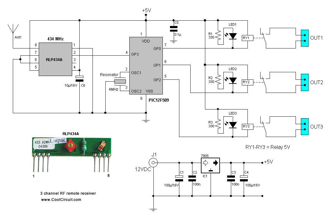
How to Make a 433MHz RF Remote Quad Circuit Diagram
Today we will build a 433MHz-based RF remote control switch with a four-channel relay to switch on or off up to four connected AC devices, such as a light, fan, electronic door, etc., wirelessly. The receiver module can be installed in any traditional or standard switchboard for controlling the devices. You can create multiple Rx circuits Making a 433 MHz, 315 MHz RF Remote Control with Relay Flip Flop. Building a hi-end remote control device using very few components today looks pretty plausible. The proposed remote control light switch circuit idea provides you with the opportunity of building and owning this amazing device through simple instructions. basic components of an RF remote control are buttons for the user to input a command, a microcontroller unit (MCU) to process the user commands into digital messages, an RF transmitter (RF TX) to modulate and transmit the message, an antenna, and a battery to provide power to the remote control. The common challenges manufacturers face in
