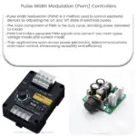
Build A Simple Pulse Width Modulation Controller PWM 55 OFF Circuit Diagram Pulse Width Modulation, or PWM, is a technique for getting analog results with digital means. Digital control is used to create a square wave, a signal switched between on and off. Understanding the Basics of Pulse Width Modulation (PWM) Power delivered to devices can be changed by raising or lowering the voltage and current. But this method does not always produce intended results. Pulse width modulation (or PWM) can be used to better control variable loads.

Pulse width modulation (PWM) is a technique used to precisely control analog devices with a digital signal. A pulse width modulation signal consists of electronic pulses that are used to mimic a changing analog voltage.
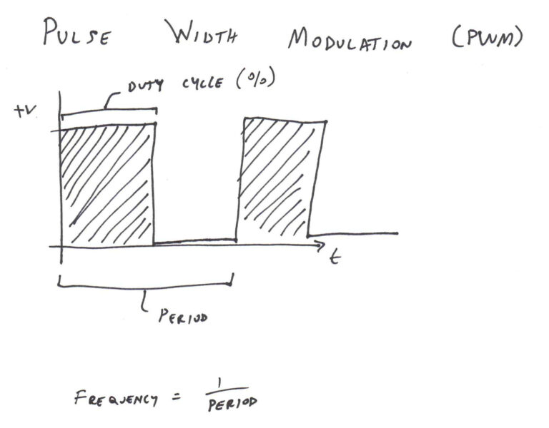
Basics of PWM (Pulse Width Modulation) Circuit Diagram
If you're into electronics, you've probably heard of Pulse Width Modulation (PWM). It's a technique used to control the power delivered to electrical devices, especially motors, LEDs, and other components that require precise control. Today, we're going to dive deep into building a simple PWM generator. Whether you're a beginner or an experienced tinkerer, this guide will walk you through the
Pulse width modulation PWM: PWM stands for pulse width modulation which consists of a square wave with the help of which we can control the up or high time. It is simple but digital way to control the digital signals that we use to vary the energy that is send to a load or to encode information within the signal.
Pulse Width Modulation (PWM) with NI myDAQ or ELVIS II Circuit Diagram
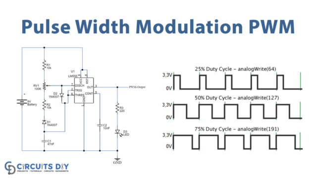
The Basics of PWM Signal Generation PWM Signal Generation is key in many fields, from audio to motor control. It uses microcontrollers to create a square waveform. By changing the pulse width, you can control the voltage to devices precisely. Generating PWM Signals Microcontrollers use analogWrite () to make PWM. This function lets you send signals with duty cycles from 0% to 100%. For example In this tutorial, we'll walk you through the basics of Pulse Width Modulation (PWM) and how to create a stm32 project for generating PWM signals using Timer peripheral. We will also create a LED dimming project using PWM technique.
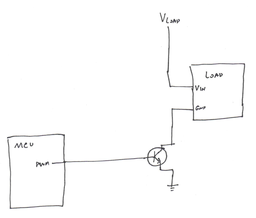
However, one of the most preferred and simple ways is by using a Pulse Width Modulation (PWM) circuit. The PWM (Pulse Width Modulation) is a technique used in driving inertial loads for a long time. The use of pulse width modulation in controlling motor drivers comes with several advantages. In Electronic Engineering, Pulse Width Modulation, or PWM, is a commonly used technique for effectively controlling the power supplied to electrical devices. In order to attain a desired average voltage or power level, the principle of pulse width modulation (PWM) is used for a periodic signal, which is usually a square wave.