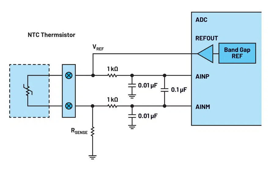
Adafruit Learning System Circuit Diagram A Basic Thermistor Circuit. Let's build a basic thermistor circuit to see how it works, so you can apply it to other projects later. Since the thermistor is a variable resistor, we'll need to measure the resistance before we can calculate the temperature. However, the Arduino can't measure resistance directly, it can only measure voltage. Sensors, Thermocouples, RTD Circuits and Thermistors A complete listing of products offered by Microchip Technology Inc. and their corresponding data sheets can be found at www.microchip.com. Precision Temperature Measurement with Silicon IC Sensors, Thermocouples, RTDs and Thermistors 6 Temperature Sensors Design Guide Temperature Sensors This circuit acquires a 12-bit level of precision across a ±25°C temperature range typically, with the nominal temperature of the thermistor at the R 25 value. USB based temperature monitor The signal path in the circuit solution starts with the low-cost, 4.7 kΩ thermistor followed by Analog Devices' low-cost ADuC7023 microcontroller.

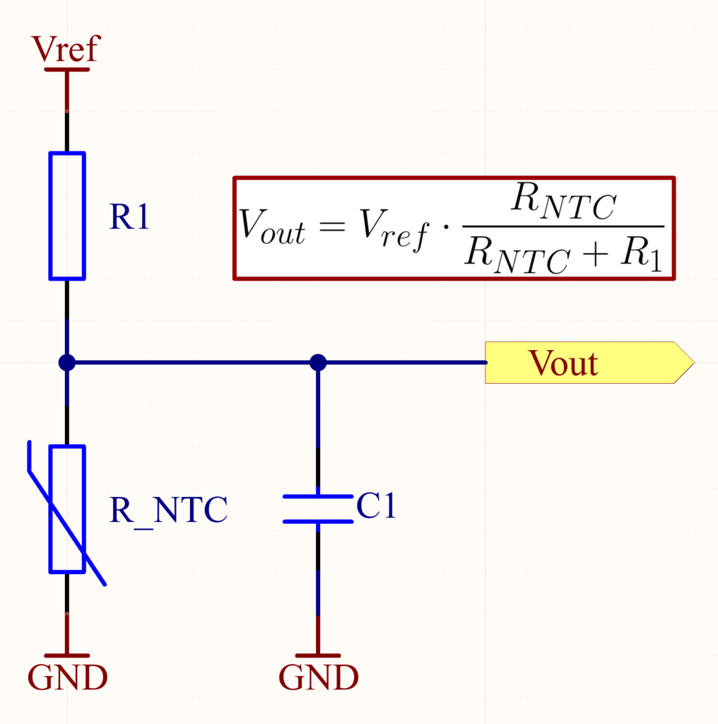
Design Description This temperature sensing circuit uses a resistor in series with a negative-temperature-coefficient (NTC) thermistor to form a voltage divider, which has the effect of producing an output voltage that is linear over temperature. The circuit uses an op amp in a non-inverting configuration with inverting reference to
Accurate Temperature Measurement Using an NTC Thermistor with an ... Circuit Diagram
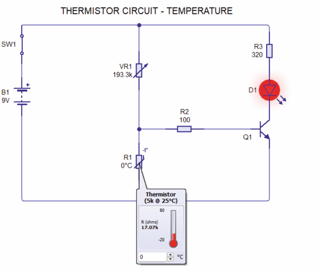
Temperature sensing with PTC thermistor is chosen based on the temperature range and the PTC's value. 2. Operate within the linear output voltage swing (See A OL specification) to minimize non-linearity errors. 3. The reference voltage, Vref, can be created Step-by-step circuit design of common op amp building block circuits. TI Designs The following simple thermistor based temperature indicator does exactly this. The value of R3 is low and that of R4 is high at a comparatively low temperature. During the positive half cycle of the mains voltage, there will be a voltage across R3-D3 that is high enough to illuminate the green LED. This circuit is very sensitive to heat since we connected two transistors as a Darlington pair. Other than that we have used an LED along with a current limiting resistor, a variable resistor, and a thermistor. Thermistors are used to limit the passage of current through them according to the temperature.
Temperature sensing with NTC thermistor is chosen based on the temperature range and the NTC's value. 2. Operate within the linear output voltage swing (See A OL specification) to minimize non-linearity errors. 3. The reference voltage, Vref, can be created Step-by-step circuit design of common op amp building block circuits. TI Designs