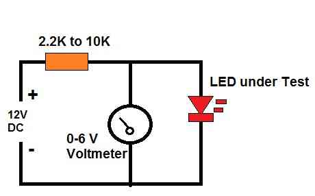
12v dc voltage drop calculator Circuit Diagram For under voltage adjust to desired operating voltage. When the voltage drop the LED will turn off. Fig. 9 TL431 under-voltage detector with opto-coupler. Fig. is a demo circuit that will turn an LED when Vin drops below the value set by the 100K pot. An optocoupler is connected in series with the indicator LED for connection to a microcontroller.

Below is an example of an End of Line voltage drop calculation: End of Line Voltage Drop Fire Alarm Diagram notes: We will assume that the terminal cut-off voltage is .5 volts below the 20.4 VDC giving us a voltage of 19.9. Use the wire lengths shown in the diagram; V1=85mA / V2=75mA / V3=115mA / V4=100mA The circuit is using #12 AWG wire

Voltage Drop Calculations of Fire Alarm System Circuit Diagram
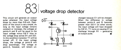
A voltage drop of [the through-current (I1)] × [input resistor (R2)] is caused by the through current, and the input voltage to descends, when the output switches from "Low" to "High". When the input voltage decreases and falls below the detection voltage, the output voltage switches from "High" to "Low".
Today we will be talking about the simple voltage level detector circuit. Its main purpose is to detect if the voltage rises above a certain point. Despite its simplicity, this circuit is an excellent way to learn about comparator circuits. We will use the LM741 OP-AMP as the main component of this circuit. This chip is a very popular general
How to Build a Voltage Sensor Circuit Circuit Diagram
But, the voltage sensor's datasheet clearly states that the maximum recommended output resistor value should be 190 Ω, so bad luck there. A 100 Ω is used instead, and the maximum voltage drop of the measurement resistor is will be 3.5 V. This value can be rescaled using an operational amplifier (op-amp) which we will take a look at next. Help with designing a universal voltage change detector. The input voltage as well as the Pull up resistor could be differential. Basically i want to output a digital signal when the voltage drops 0.5 volt regardless of the input voltage. Eg.. V drops from 14 to 13.5 output=1 This is a voltage sensor circuit, where if we get to a certain level of voltage, then the output will turn on. And we can build a voltage sensor circuit, simply with a voltage comparator chip or an op amp that can function as a voltage comparator. A voltage comparator chip is a chip that contains 1 or more op amps. Using a single op amp, we can